Chinese
 English
 français
 Deutsch
 italiano
 español
 português
 Nederlands
 한국의




- ホーム
- >
カテゴリ
熱いプロダクト
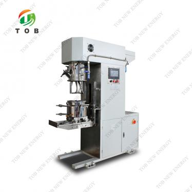
Patent CN215610864U - Large-Capacity Vacuum Slurry Mixer
Oct 23,2026A lift-and-seal twin-barrel vacuum mixer whose three stirring-rod sets, wall scrapers and stage-controlled speed turn battery raw materials into a fully dispersed electrode slurry.
Full specification and drawings: CN215610864U on Google Patents
In lithium-ion battery production, the mixing and dispersion of the cell slurry determines more than 30% of final product quality - the specification calls it the most important link in the entire production process. Yet the mixers in use delivered only an average stirring effect: under-dispersed active particles travel unevenly between the two electrodes, and that unevenness follows the slurry all the way into the coated electrode, the dried coating and finally cell capacity and cycle life.
CN215610864U, filed on 26 August 2021, attacks the problem at the machine level: a vacuum mixer whose slurry chamber is sealed by lifting one barrel onto another, whose stirrer combines three sets of stirring rods with three wall-scraping bars, and whose reducer lets the controller assign a different stirring speed to each stage of the batch.
Patent Information
| Publication number | CN215610864U |
| Title (original) | 一种搅拌效果好的大型电池原料搅拌机 (Large-Capacity Vacuum Slurry Mixer) |
| Inventors | Huang Zhengyao (Dany Huang); Chen Lucai (Tobey Chen) |
| Current assignee | XIAMEN TOB NEW ENERGY TECHNOLOGY Co., Ltd. - the registered entity of TOB NEW ENERGY |
| Filing date | 26 August 2021 |
| Grant date | 25 January 2022 |
| Document type | Utility model (granted, kind code U) |
| Legal status | Active |
| Anticipated expiration | 26 August 2031 |
| Drawings | 6 figures |
The Production Problem This Patent Solves
Cathode slurry is built from binder, conductive agent and cathode material; anode slurry from binder and graphitic carbon. Each batch is a succession of liquid-liquid and liquid-solid mixing, dissolving and dispersing steps, all accompanied by changes in temperature, viscosity and the surrounding environment. If the granular active materials are not dispersed evenly, lithium-ion transport between the electrodes suffers - and so does every downstream process.
The specification names the weak point directly: the stirring effect of the cell slurry was only ordinary in the equipment then available, and slurry that is not fully homogenised makes battery quality uneven across the market. The device in CN215610864U is designed to close that gap before the slurry ever reaches the coater.
How the Mechanism Works
Lift-and-seal twin-barrel chamber
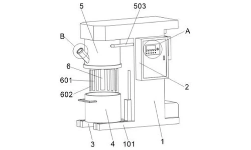
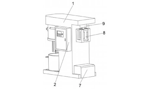
The mixer has no bottom door. A lower mixing barrel (4) sits on a lifting table (3) inside the base (101) of the frame (1). A lifter (7) at the lower right of the frame raises the table until the lower barrel meets the fixed upper barrel (5), where a sealing ring between the two barrels closes the chamber so it can be evacuated. The lower and upper barrels are made of SUS304 stainless steel, chosen in the specification for stable physical and chemical behaviour and corrosion resistance.
Stirrer with rods and wall scrapers
Inside the upper barrel, the stirrer (6) carries three sets of stirring rods (601) on its inner side and three wall-scraping bars (602) on its outer side. The rods disperse the slurry; the scrapers lift material off the barrel wall and push it back into the flow, so no stagnant layer is left at the wall and the batch is stirred thoroughly rather than merely agitated in the middle.
Vacuum line, sight port and control
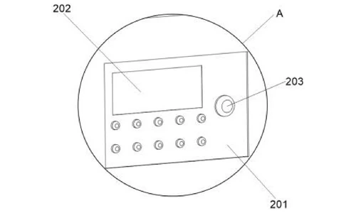
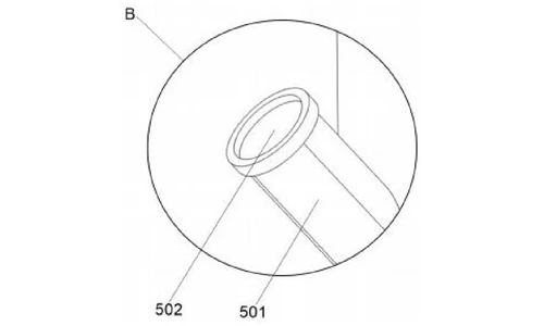
A vacuum line (503) connects the front of the upper barrel to the vacuum unit inside the frame, so air is drawn out of the sealed chamber before and during mixing. A sight port (501) at the lower left of the upper barrel - closed by a sealing cover (502) with a tempered-glass centre - lets the operator watch the slurry in real time. The controller (2) on the front of the frame carries an LED display (202) for the working parameters and an emergency stop button (203).
Chain-driven reducer and stage-controlled speed
The motor (8), fixed to the frame wall through a motor fixing seat, sits above a reducer (9). The reducer passes power to the stirrer through a chain, which the specification notes runs smoothly and quietly. Because the reducer output speed is adjusted from the controller, the machine can assign different speeds to different stirring stages of the same batch - the second half of the specification's two-part answer to mixing quality.
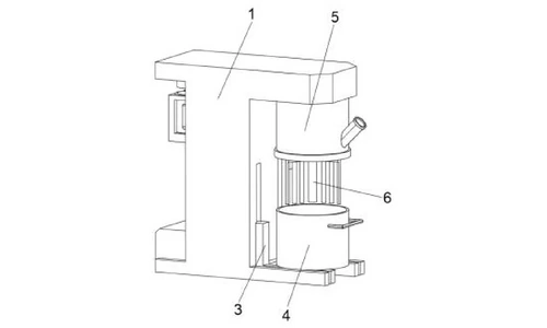
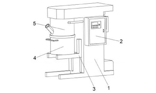
Operating sequence
Raw materials are loaded into the lower barrel while it stands on the lowered table. The lifter then raises the lower barrel into sealing contact with the upper barrel, the vacuum unit evacuates the chamber, and the motor starts. The stirrer runs the slurry through the assigned speed stages while the operator watches through the sight port. When mixing is finished, the table descends, the barrels separate, and the batch is discharged.
Claimed Benefits
| Benefit | Mechanism responsible |
|---|---|
| Thorough slurry mixing, no stagnant wall layer | Three stirring-rod sets plus three wall-scraping bars on the stirrer |
| Higher slurry quality per batch | Controller-adjusted reducer output speed, staged across the mixing run |
| Airtight, corrosion-resistant process chamber | Lift-sealed SUS304 barrels with a sealing ring at the joint |
| Real-time visual monitoring while mixing | Sight port with tempered-glass sealing cover |
| Stable, quiet power transmission | Chain drive from the reducer to the stirrer |
How It Compares with Conventional Slurry Mixing Vessels
Each slurry batch is a succession of mixing, dissolving and dispersing steps with changing temperature and viscosity. If granular active material is not fully dispersed, electrode quality suffers - so the mixer itself is where consistency is won or lost.
| Dimension | Conventional approach | This patent design |
|---|---|---|
| Mixing action | Single stirrer, stagnant layer at the wall | Three stirring-rod sets plus three wall-scraping bars on one stirrer |
| Speed control | Fixed speed for the whole batch | Chain-driven reducer with controller-staged speed across the mixing run |
| Process seal | Open or clamp-type vessel, leak and corrosion risk | Lift-sealed SUS304 twin barrels with a sealing ring and vacuum line |
Where This Technology Is Used Today
This patent covers the slurry-mixing architecture behind TOB's large vacuum mixers. The combination it protects - a lift-sealed barrel chamber, wall-scraping agitation and stage-controlled speed - is how our mixing equipment delivers the homogeneous electrode slurry that coating quality depends on.
- 2000L planetary vacuum mixer and dispersing machine - production-scale mixing and dispersion for battery slurry
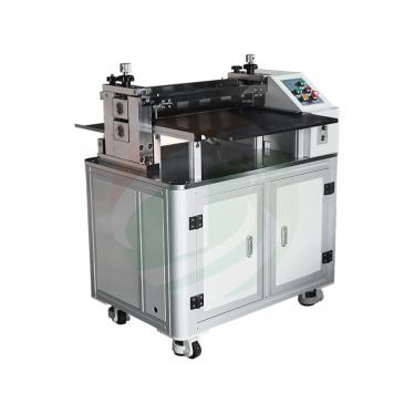
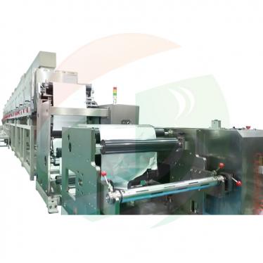
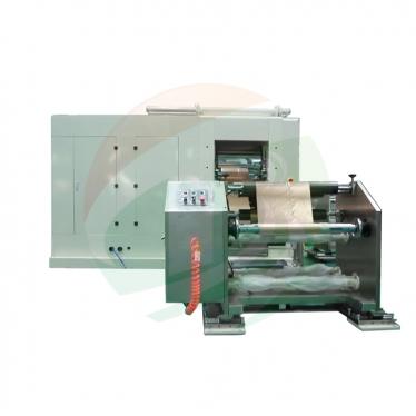
- Electrode preparation equipment - slurry mixing, testing, coating, rolling and slitting equipment
Related equipment enquiries: request a quote
Frequently Asked Questions
What does patent CN215610864U cover?
It covers a large-capacity vacuum slurry mixer for battery raw materials, built around a lower mixing barrel that is lifted into sealing contact with a fixed upper barrel, a stirrer with three sets of stirring rods and three wall-scraping bars, a vacuum line to the sealed chamber, and a chain-driven reducer whose speed is staged by the controller.
Why is slurry mixing quality so important in battery production?
The specification states that slurry mixing and dispersion influence more than 30% of final product quality in lithium-ion battery production. Unevenly dispersed active particles disturb lithium-ion transport between the electrodes and degrade the coated electrode, cell capacity and cycle life.
Why does the stirrer carry wall-scraping bars as well as stirring rods?
The three sets of stirring rods disperse the slurry, while the three wall-scraping bars lift material off the barrel wall and return it to the flow. Without scrapers, a stagnant layer builds up at the wall and the batch is never fully homogenised.
How does the mixer vary the stirring speed between stages?
The motor drives the stirrer through a reducer connected by a chain. The controller adjusts the reducer output speed, so different stirring stages of the batch run at different speeds - the mechanism the specification credits for further improving slurry quality.
What materials are the mixing barrels made of?
The lower and upper barrels are made of SUS304 stainless steel, which the specification describes as stable in physical and chemical behaviour and resistant to corrosion; a sealing ring between the barrels keeps the chamber airtight during vacuum mixing.
Is patent CN215610864U still in force?
Yes. It is Active, filed on 26 August 2021 and granted on 25 January 2022, with anticipated expiration on 26 August 2031.
Full specification and drawings: CN215610864U on Google Patents
 購読する